
Martin wrote:
Wow! That is one seriously impressive set of instructions..
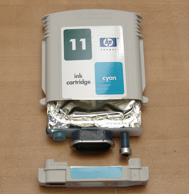
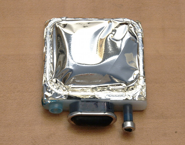
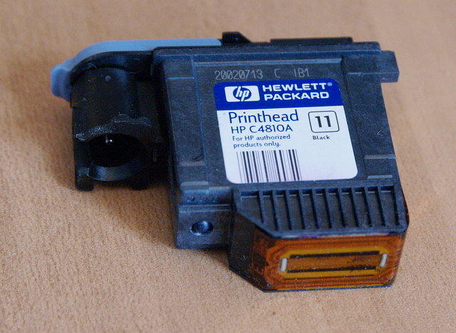
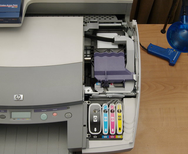
I see now what you mean about the fittings although I do know from experience that the key issue I had was drilling through the bag which was a right pain in the patookis.
Quote:
I think I'll have to give this glue of yours a try though with my own approach... I've just opted to change the tubing I've been using for a Tygon R3605 lab type of 1/32" ID coupled with the elbow fittings I noted in the other thread.
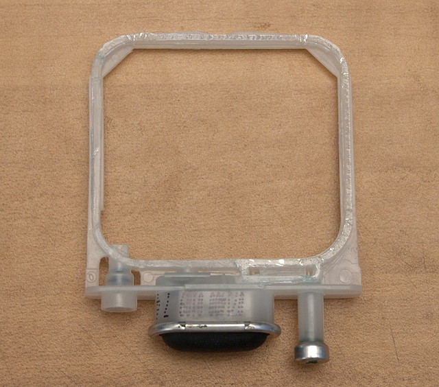
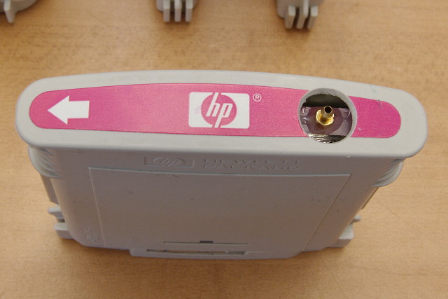
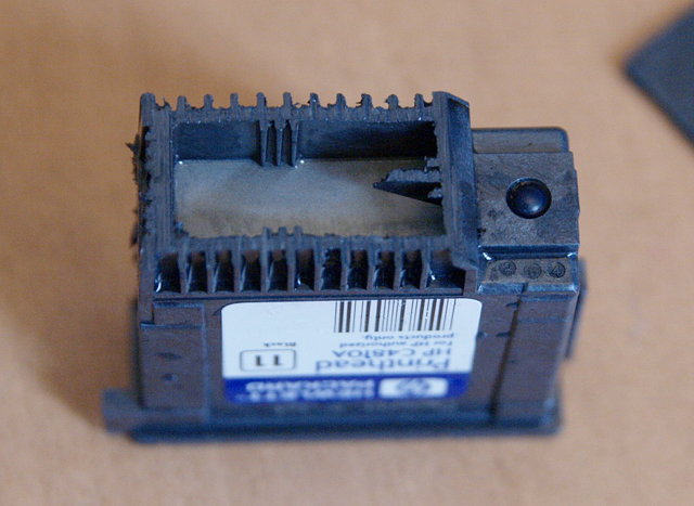
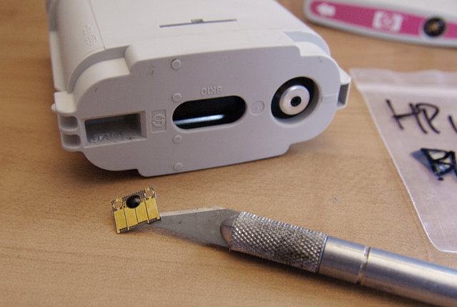
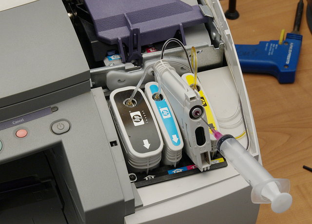
My approach is via the filling port and as you guessed it's easy enough to manage if you slice off the raised part around that area. That said the space available under there is very tight so I'm playing with a way to remove an additional 1mm of depth around the fill hole. That would allow the fitting to sit lower and gain more clearance.
Quote:
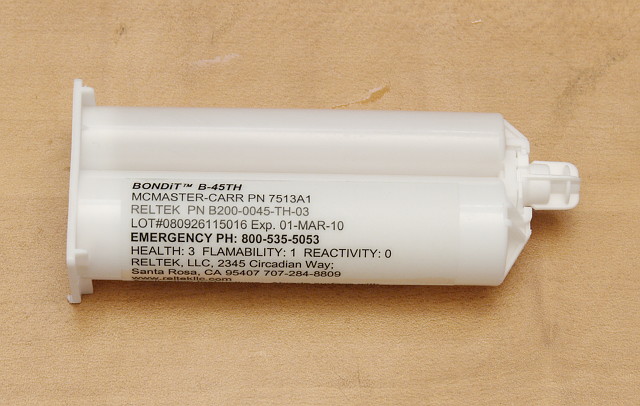
Obviously it'd be easier to explain with pictures but having seen this epoxy I think it's going to be worth a small investment as a trial run to see if it's better than the thread locker I got and do it all properly with pictures then
Now I need to find a UK supplier for that epoxy...
xiphmont wrote:
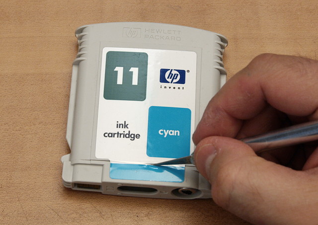
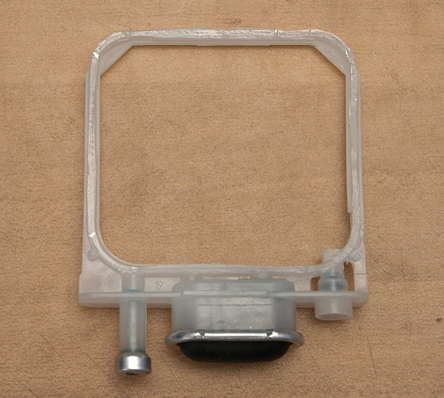
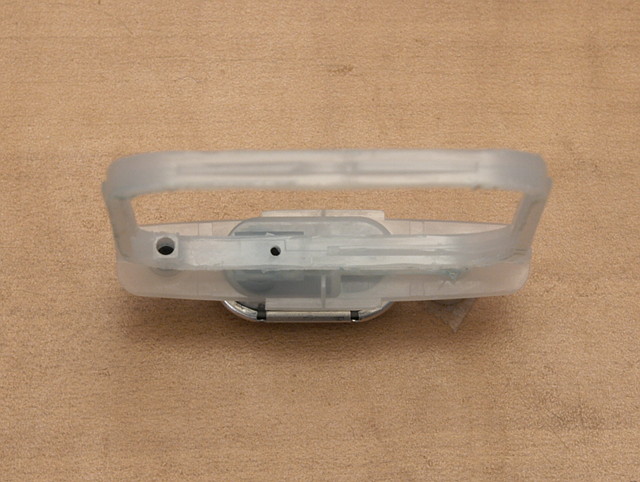
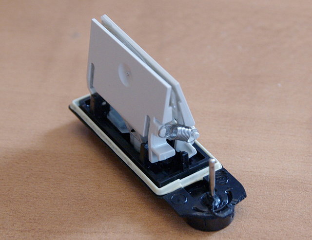
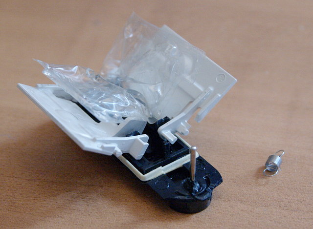
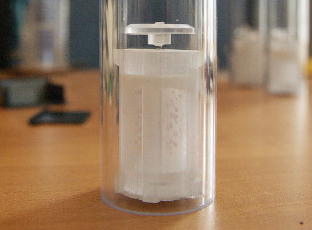
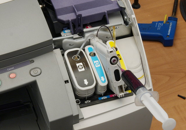
I blew into the bag through the ink port to puff it out as far as it would go, resealed it, then drilled. Doing it all very slowly by hand, I had all the control I needed, and I'm 8 for 8 so far. I should probably add that to the instructions. The pictures for that part are 'staged' so the bag had already deflated a bit.
Quote:
Quote:
My approach is via the filling port (snip)
I tested that idea out on a scratch cartridge, and even trimming flush to the frame it looked like it would be a very tight fit. If I used a striaght adapter, the tubing didn't have clearance to bend without kinking, and with an elbow, it looked like I couldn't screw it down because it would hit the pump area. If you have parts that fit, it seems logical to try.
Quote:
Quote:
Now I need to find a UK supplier for that epoxy...
The stuff was pricey, but 50ml is prbably enough to do 100 or more carts easy. If you want me to buy one and forward it on to you, I'd be happy to.
Martin wrote:
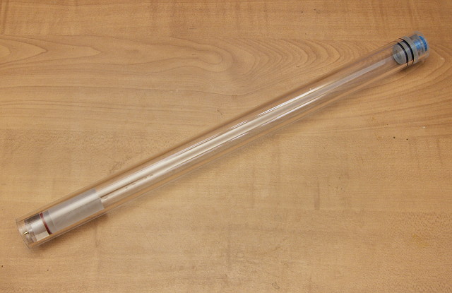
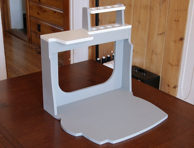
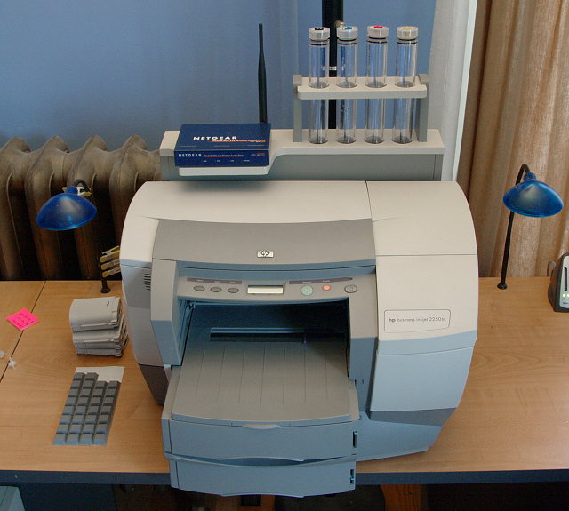
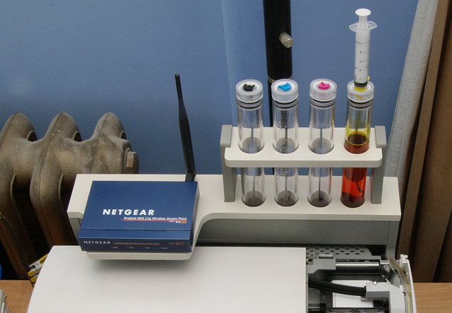
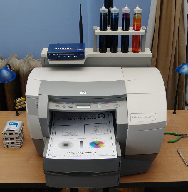
Hmm... from a practicality point of view that's an interesting design although the long tube means it'll be difficult to locate and incredibly easy to knock over... That said, presumably a good way to stop air getting into an HP system which is the whole point.
Martin wrote:
Unfortunate about the glue and on reflection sounds a lot like an epoxy I already have access to here, so I think I'll eskew the purchase for now until you've had a chance to really test it long term...
xiphmont wrote:
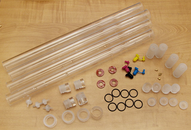
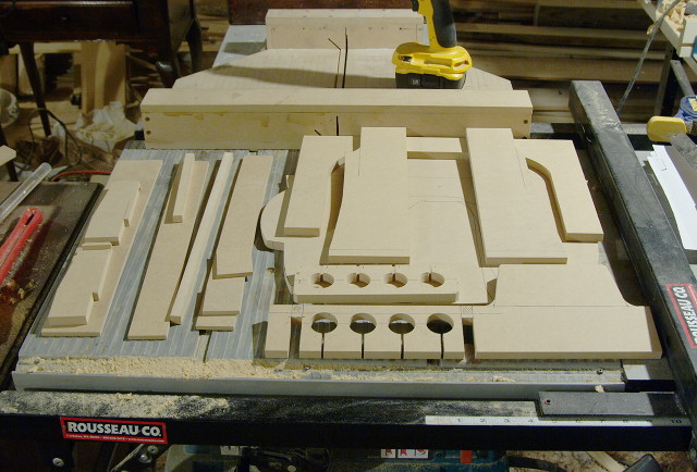
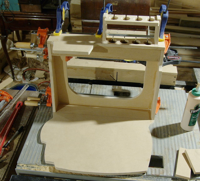
It could just as easily be shorter/fatter tubes. I purposely went for long/skinny and plan to make a mount/stand that slots them onto the back of the printers in a way that's well attached, and the printers are all backed right against walls, so there's nowhere for the whole shebang to get knocked to (the printers themselves are a good 35+ lbs). Maybe a good idea, maybe not, but certainly a design specific to this setup and location. I was sort of thinking 'control rods' when I specced it out
Quote:
I'm going to do a more controlled test directly comparing to marine epoxy, two-part silicone, and the PP superglue someone else mentioned. But I'm pretty sure at this point it was just a waste of money. Not bad, just not better than the cheaper stuff. We'll see in few days.


Martin wrote:
I feel positively inadequate now as my workshop doesn't have nearly this many tools and materials to work with but I have to say that that guide provides all the clues and input anyone would need to put together a simple but effective system.
Martin wrote:
It mirrors some of the things I've developed myself with the exception of the reservoirs which are much more simplified. In particular the reservoirs air shut off isn't included but TBH I think it's overkill as regular top ups help avoid empties whilst the pump/bulb system built into the original cartridges and printer stops you pumping air into the printer anyway...
Martin wrote:
So, my thanks for all that info... As for the "next printer"... Any ideas which one? :)
xiphmont wrote:
Martin wrote:
It mirrors some of the things I've developed myself with the exception of the reservoirs which are much more simplified. In particular the reservoirs air shut off isn't included but TBH I think it's overkill as regular top ups help avoid empties whilst the pump/bulb system built into the original cartridges and printer stops you pumping air into the printer anyway...
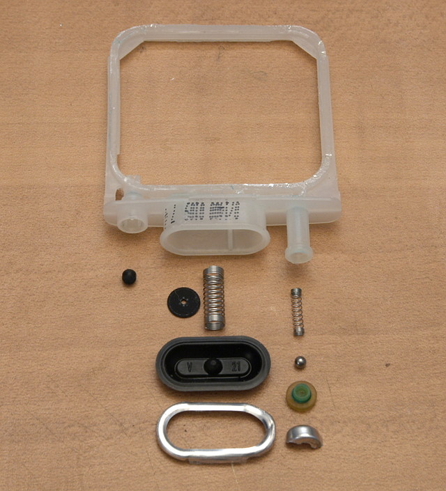
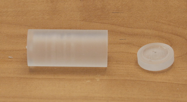
The floats definitely turned out to be more trouble than I planned for. More than they're worth? Yeah, probably.
Aw heck, I just thought of a way to make real easy simple floats that would work better and take way less space... dangit...
Quote:
As for the bulb and pump system not being able to suck in air, I'm not sure why you think so. They'd be able to pump air to the heads by accident just fine. I'm pretty sure the way the printer senses out of ink is when it pushes in the bulb, and then the bulb doesn't spring back because there's no ink [or anything else] left to suck from the sealed bag. If you know different, do say so-- I'd love to just lose the floats.
Quote:
Yeah. A few more of the same (HP Business Inkjet 2250). Eventually I'd like to have a nice personal photo printer with a CIS system, but it's not in my budget right now.
output generated using printer-friendly topic mod. All times are GMT + 1 Hour